- Measurements from 1 kΩ to 100 TΩ, with auto ranging
- 0.5% measurement accuracy
- Improved High-visibility blue LCD graphical display for menu programming and test results
- Programmable test voltage from 1 to 1000 Vdc
- Fully programmable measure cycle times
- Automatic test lead zeroing to eliminate connection errors
- Direct reading of measured resistance or current
- RS-232, Flash Drive for data storage in CSV format and uploading test setup conditions, and PLC Interfaces Standard, IEEE-488 Optional
- IET 1865 Plus LabView Driver for IEEE-488.2 and RS-232
- Proven over many years in the field
- CE option available
- Limit entry for pass/fail testing
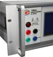
- Safety interlock and high voltage indicator for operator safety
- ASTM D 257 Volume and Surface Resistivity with 1865 Plus
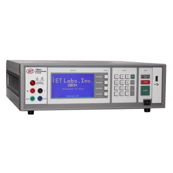
The 1865 + is the Megohmmeter for today's most challenging applications
New Significantly Improved Version of a trusted standard.
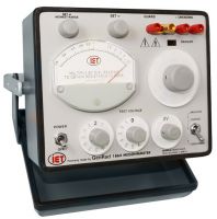
See how the 1865 Plus can be used in to calibrate your resistances standards at voltage up to 5 kV.
A System for High Voltage Resistance Measurements up to 6 kVdc.
- Ideal for calibration of IET's SRC or VRS resistance standards at voltage from 1 kVdc to 5 kVdc
- Use these SRC and VRS standards in calibration of megohmmeters such as the Fluke 1555, MEGGER MiT Series and others at 5 kVdc or other voltages.
The 1865 + Megohmmeter/IR tester, with digital display, is used for high accuracy measurements of insulation resistance on a wide variety of components, materials and electronic devices. Resistance values greater than 100 TΩ can be measured with a basic accuracy of 0.5% at DC voltages up to 1000 V.
A programmable limit makes the megohmmeter ideal for pass/fail testing in a production environment and is also adaptable for use in automated system applications with its included RS-232 Interface or optional IEEE-488 interface adapter.
Precision Measurements: The IET Labs 1865 + Megohmmeter provides resistance measurement capability from 1 kΩ to 100 TΩ (test voltage dependent) with a basic accuracy of 0.5%. To meet test requirements for a wide range of devices, the test voltage is fully programmable up to 1000 Vdc. Sensing the proper resistance measurement range is done automatically, thus eliminating setup errors; and in order to eliminate lead or fixture errors, the operator can easily initiate an automatic zeroing routine of test leads.
Easy to use: The 1865+'s menu programming system is significantly improved, simple controls and indicators combine for efficiency of test and productivity. Its multi-function keypad provides the operator with an easy way to program and make measurements.
Pass/Fail Testing: Measured results are automatically compared to an operator programmed limit for pass/fail testing. Pass/Fail indicator lights or a pass/fail output from the megohmmeter I/O interface provide a clear indication of the measured results.
Program and Data Storage: Test setup conditions and measured results of the megohmmeter can be stored in CSV format for easy use with Microsoft Excel. Storage options include:
- 512 MB of internal instrument memory for storage of setups
- A computer (via the RS-232 interface)
- A flash drive (via the USB host port)
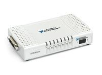
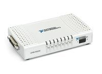
Automated Testing: For automated system applications, the 1865+ Megohmmeter includes an RS-232 interface for control and data collection and an I/O interface connection with remote start and pass/fail outputs. An optional IEEE-488 to RS-232 adapter is also available (or can be added later), which enables the 1865 to be remotely controlled by a computer with ieee-488 interface.
Resistance or Current Display Mode: Besides a readout of insulation resistance in ohms, the operator can select a display mode for reading the measured current directly .
Safety Features: The 1865 + Megohmmeter provides safety features such as current limiting, a warning indicator when high voltage is active, and safety interlock, all for protection of the operator.
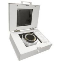
Component Test Fixture: An accessory fixture is available for use with the 1865+ Megohmmeter which accommodates a variety of component types, including radial, axial and chip components. Its shielded case reduces electrical noise and interference and includes a cover interlock switch and remote start for maximum operator safety.
Why Buy?
- Volume and Surface Resistivity Measurements in conjunction with 1865-11
- For precision high resistance measurements over a wide voltage range
- For automated testing requiring remote start and pass/fail output
- To data log test results via RS-232, Flash Drive or IEEE-488 interface adapter
Product Package
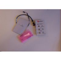
The following accessories come standard with the megohmmeter:- 150073 1865 Instruction Manual
- 4200-0300 AC Power Cable
- 800014/15 Capacitor Adapters (100kO & 1MO)
- 520049 Power Line Fuse (2.5A, 250V)
- 630019 Interlock Connector
- Calibration Certificate Traceable to SI
1865+ Megohmmeter Basic Specifications
(Full specifications can be found on datasheet)Resistance range:
1x10⁶ to 1x10¹⁴ Ω at 1000 Vdc
1x10⁵ to 1x10¹³ Ω at 100 Vdc
1x10⁴ to 1x10¹² Ω at 10 Vdc
1x10³ to 1x10¹¹ Ω at 1 Vdc
No of ranges: 7 manually settable plus auto-ranging
Voltage range: 1 to 1,000 volts, programmable in two ranges
Voltage accuracy at front panel connectors:
1 - 100 V: 1% of setting + 1% Resolution: 25 mV
100 - 1,000 V: 1% of setting + 2 % Resolution: 250 mV
Resistance accuracy: ±[0.45% +{(RX/VX)(0.0005FS + 2pA) + 30Ω/RX}100%]:
RX = Measured resistance in ohms
VX = Programmed voltage in volts
FS = Full scale current range in amperes
Measuring current: 0.1 pA (10-13 A) to 1 mA (10-3 A)
Current accuracy at front panel connectors:
1 nA to 1 mA ±[0.5% + (0.0005 FS + 2 pA)]
100 pA to 1 nA ±[1% + (0.0005 FS + 2 pA)]
1 pA to 100 pA ±[10% + (0.0005 FS + 2 pA)]
Short-circuit current:<2 mA
Input impedance: 5 kΩ, ±5%
Output voltage impedance: 1 kΩ, ±5%
Measurement limits: Pass/Fail (1 limit)
Interfaces: Standard: RS-232, I/O port with safety interlock Optional: IEEE-488 interface adapter & Data/Program storage via USB port
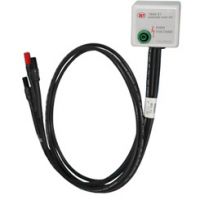
Input terminals: Four sheathed banana jacks, front-mounted (with optional rear-mounting) + unknown (red) - unknown (black) guard (blue) ground (green)