In the GenRad Tradition...
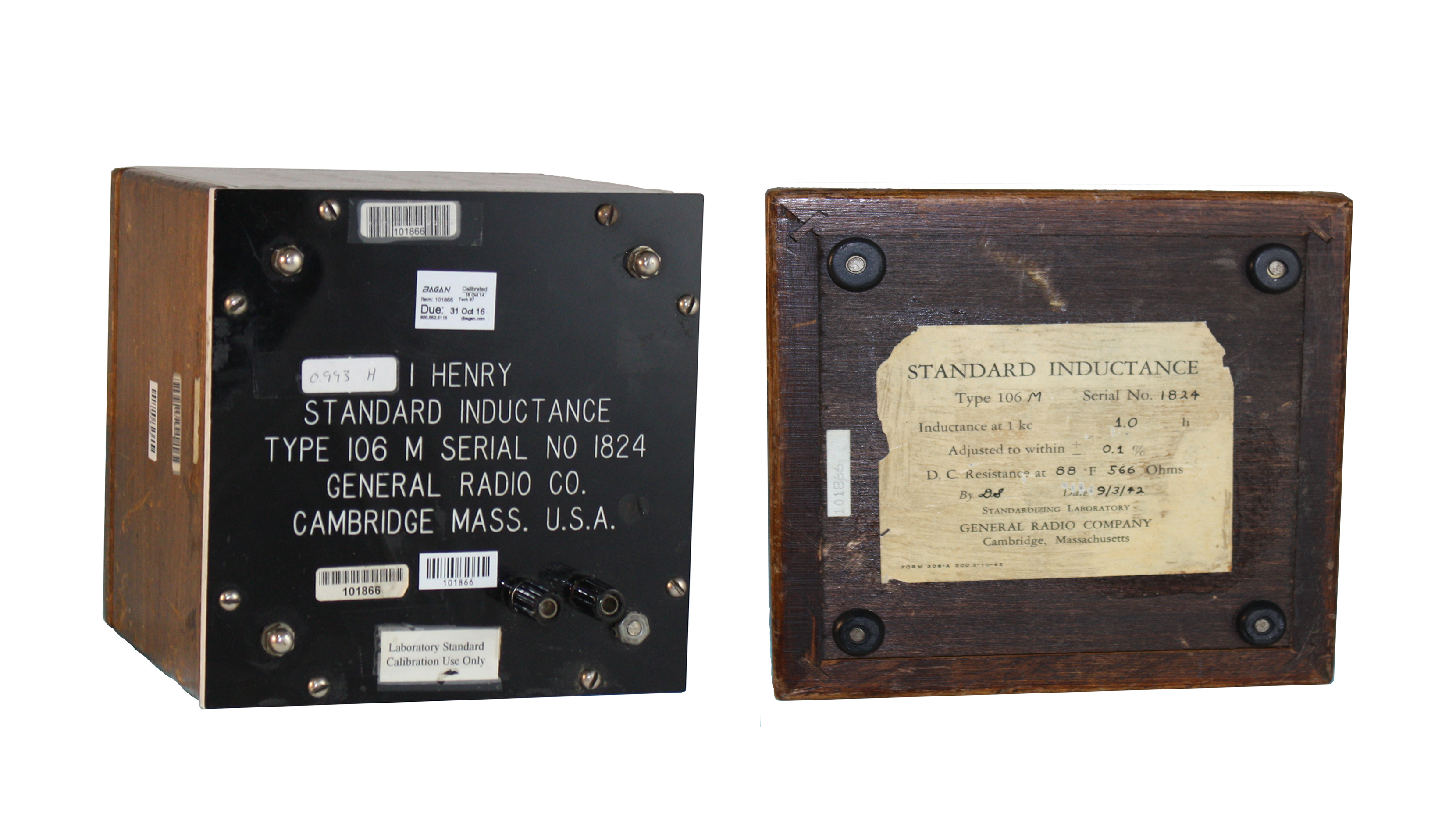
Special thanks to Henry P Hall for the pictures and content.Type 106-M
GR was known for its complete line of resistance, capacitance and inductance standards and decade boxes. The 160-M Standard Toroidial inductor, is the predecessor to the GenRad 1482 Series of standard inductors that have been the standard for inductance over the decades. The 1482 Standard Inductors are manufactured by IET Labs today.
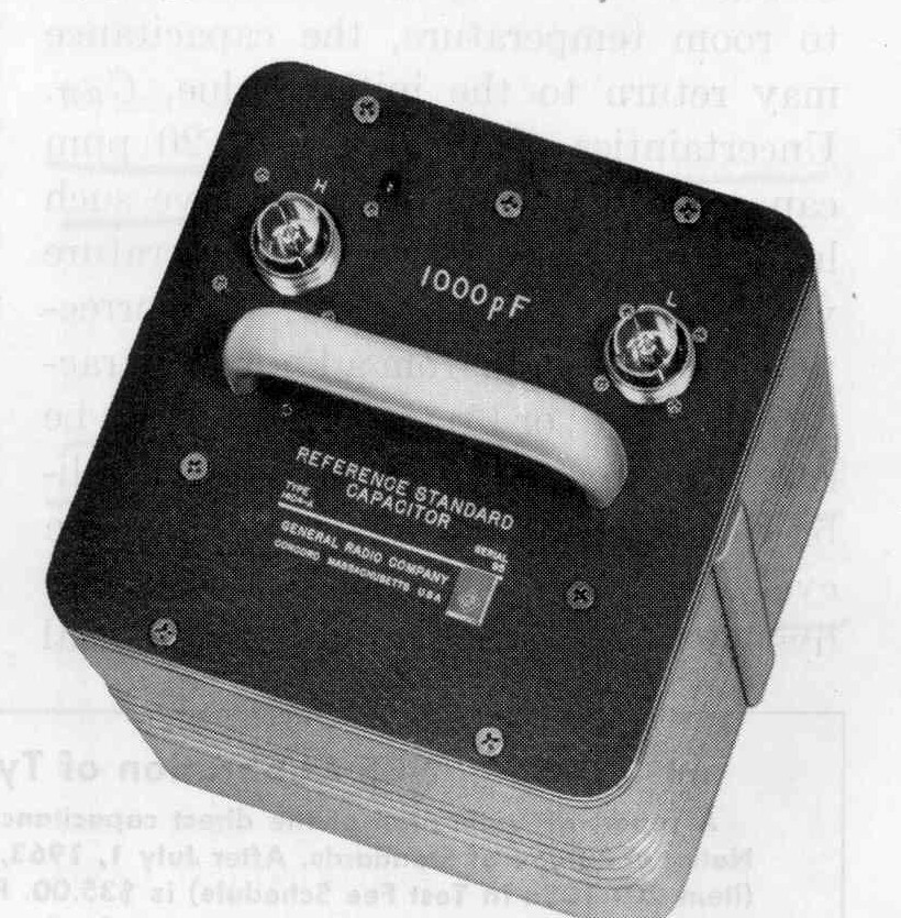
Type 1404 Standard Capacitor
GR was known for its complete line of resistance, capacitance and inductance standards and decade boxes. The 1404 precision standard capacitor, designed by J. F. Hersh and announced in 1963, was one of the most popular and used in standards labs around the world. It was an “air” capacitor (actually dry nitrogen) that used Invar steel plates to get a low temperature coefficient and get excellent stability. It came in values of 10, 100 and 1000pF. GR made other standards from .001 pF to 1 Farad, most of which are made by IET Labs today.
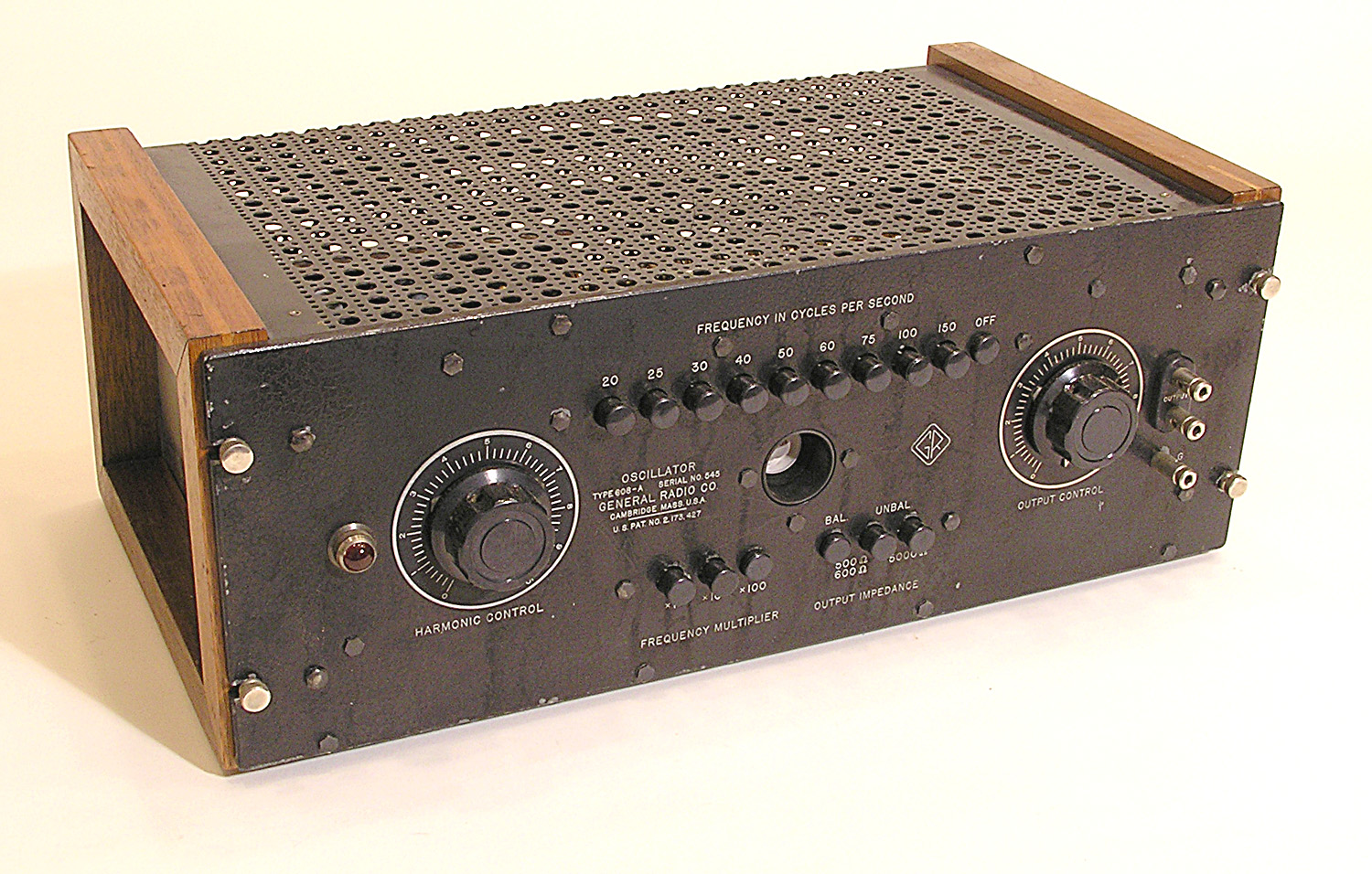
Type 608 Oscillator
The GR 608 was the world’s first R-C oscillator, announced in April of 1939. It was designed by H. H. Scott who worked for GR at that time. It used a separate twin-tee R-C network for each frequency which was selected by a push button. Hewlett-Packard licensed the GR patent even though their famous oscillator used a variable R-C Wien bridge instead of fixed twin-tees. The HP oscillator used a lamp to stabilize the signal level. The 608 had no similar device but instead had a “Harmonic Level” control that was adjusted to get the circuit to just barely oscillate to get low distortion.
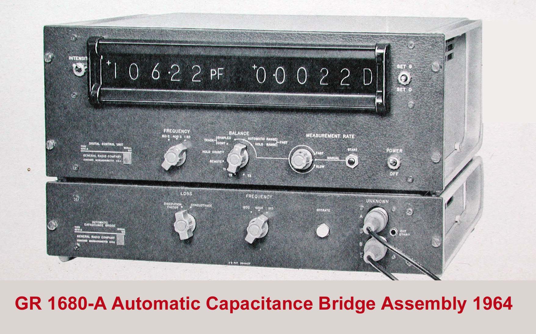
Type 1680 Automatic Capacitance Bridge
The 1680, designed by R. G. Fulks, was the first automatic bridge balanced electronically. It was announced in 1965. Not only could it measure and sort capacitors rapidly, but perhaps more important, it could also be controlled by an external computer. This ability resulted in its use in many automatic systems which were among the first automatic test equipment (ATE) systems. It was often used with the DEC PDP-8 mini-computer.
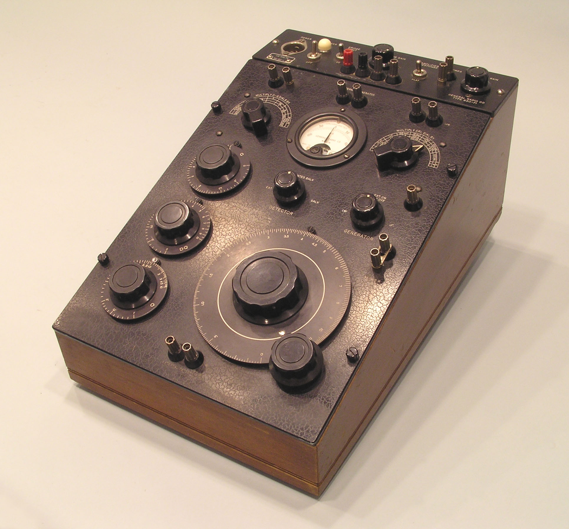
Type 650-A Impedance Bridge
The 650 was the first instrument that could measure, resistors, capacitors and inductors. Before that, separate bridges were used. This famous long-lived bridge was designed by R. F. Field and announced in 1933. It wasn’t replaced in the GR line until 1959. Early versions used four large A cells for power and a vibrating, microphone “hummer” as a 1 kHz AC source. In 1941, an electronic R-C oscillator and selective detector unit designed by H. W. Lamson fitted in the battery compartment.
Type 1650-A Impedance Bridge
The 1650-A, designed by H. P. Hall, finally replaced the famous 650 in 1959. Like the 650, it was only 1% accurate, but never-the-less became a GR best seller. It used transistors in its oscillator and detector and as a result could be supplied by just four D cells, making it smaller and portable. It was the first GR instrument to use used the clever “flip-tilt” cabinet designed by H. C. Littlejohn. It was modified slightly by C. D. Havener in his 1650–B in 1968. 1650s were in the last general GR catalog in 1978.
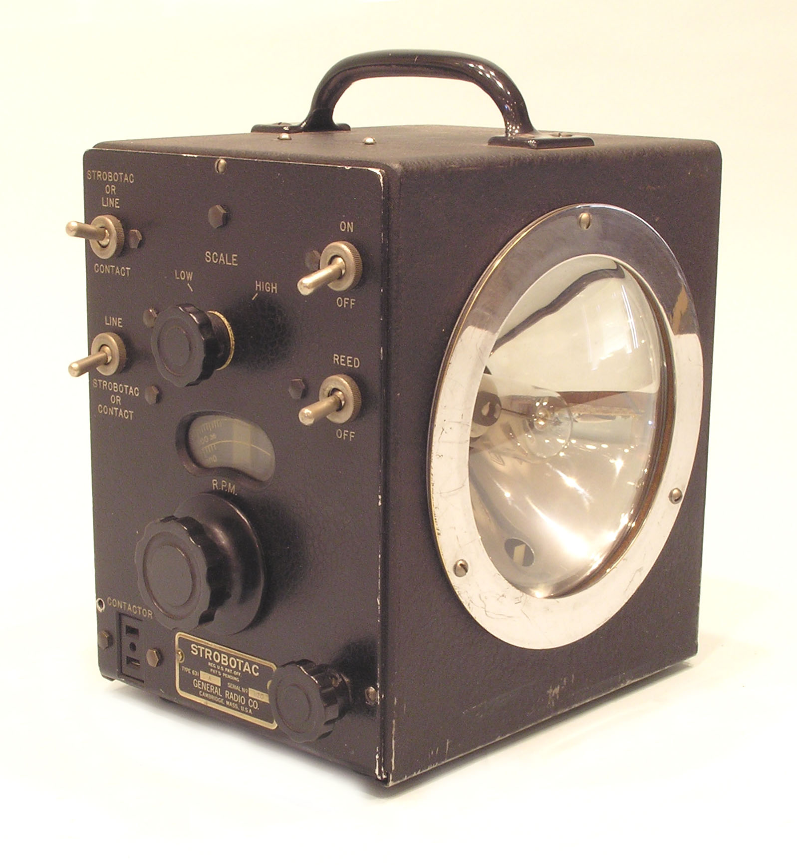
Type 631 Strobotac
GR made earlier strobes designed by GR engineers with the help of MIT’s Harold Edgerton AKA “Papa Flash,” but the Type 631-A (1935), by H. H. Scott and H. Wilkens, was probably the most famous. Its rapid flash and calibrated frequency made it a good tachometer to measure the speed and to study the behavior of moving machinery. It was also used in high-speed photography. Examples of that are Edgerton’s famous photos of a bullet going through an apple and a balloon bursting. Later GR strobes that are faster and brighter are now sold by IET Labs.
Type 403 Standard Signal Generator
The 403 is believed to be the first signal generator, the first in a long line of such instruments made by GR and other companies. It was designed by Lewis Hull who was on loan from the Aircraft Radio Co. It was first mentioned in GR Catalog E (1928). It provided a calibrated low-level, modulated, wide-band, RF signal to test radio receivers. A critical part of these generators is their attenuator which needed to be carefully shielded to get microvolt level signals. The 403 provided signals as low as 2 microvolts.
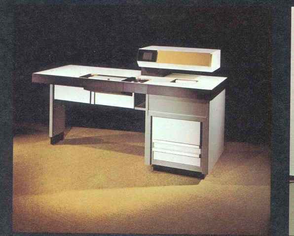
Type 1790 Logic Circuit Tester
The 1790 was the first circuit board tester. It was designed by R. Cvitkovich and M. Fichtenbaum and announced in 1970. It was major step in the history of automatic test equipment (ATE). Several other GR circuit board testers followed including the GR2270 In-Circuit/Functional Test System, the first of its kind. GR was a leader in circuit board testing for many years, and when GR was sold to Teradyne, GR (by then GenRad) had the largest installed base of circuit board testers in the world.
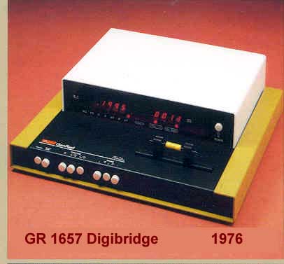
Type 1657 Digibridge®
The 1657 Digibridge®, designed by Gipe, Henry Hall and Sullivan and announced in 1976, was the first digital impedance meter of its kind. It used a microprocessor to calculate the various impedance parameters from measured, quadrature AC voltages. This patented principle was widely copied and several companies paid to use the idea, including Hewlett Packard who paid GR a million dollars. IET labs makes several of the later GR designed Digibridges® which have many more features and improved accuracy. The newest, the 1693, is the most accurate such meter available.
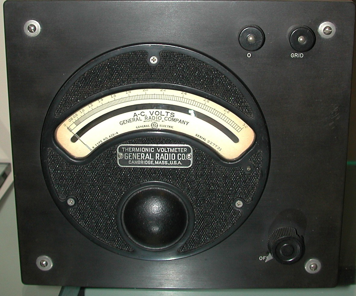
Type 426-A Thermionic Voltmeter
The 426-A, introduced in 1928, was the world’s first commercial vacuum-tube voltmeter. Its main advantage was its extremely high input impedance. The 426 measured AC only and had an accuracy of 3% to 300 kHz. It used a single triode tube in a bridge circuit. The panel zeroing control adjusted the vacuum tube to cut off so that the meter responded to positive voltages only. Thus its reading was proportional to the positive average, but it was calibrated in the RMS of a sinusoidal signal. The meter was powered by a single 22.5 V battery and thus completely portable.
Type 497 Tube Mount
The 497 was part of the first GR oscilloscope, announced in 1931, it was among the first in the US. There were two other parts, the 496-AM a power supply and of course the CRT itself, the type 478. It could be used with the 506-A Bedell Sweep Circuit and with the Type 514 Amplifier. Since It had no amplifier itself, its bandwidth depended only on the tube response making it useful to 30 MHz.. The next GR ‘scope, the Type 635 (designed by J. D. Crawford and announced in 1933), put the tube and the power supply in the same wooden box, but still had no internal sweep circuit or amplifier.
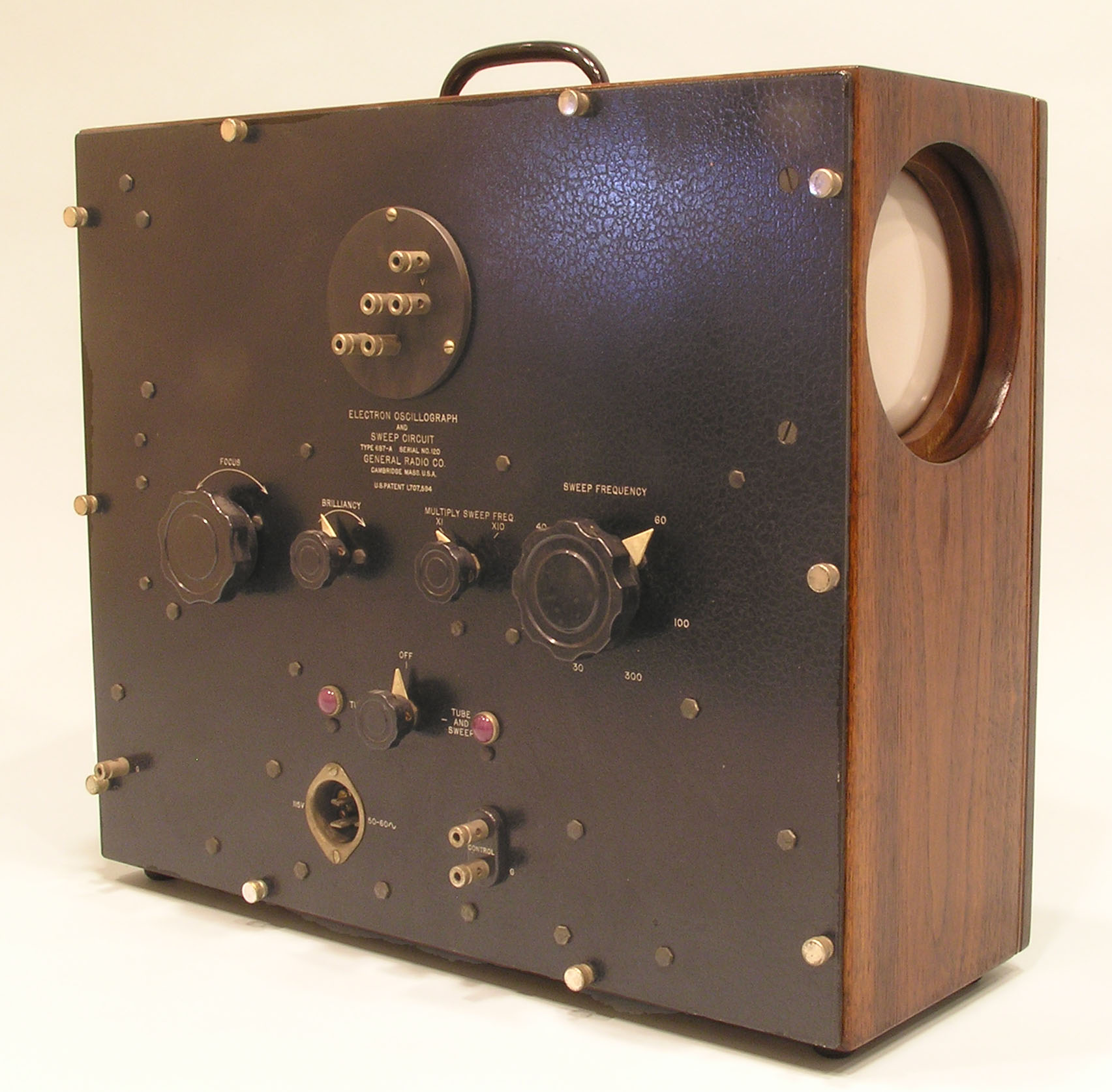
Type 687 Oscilloscope
The 687 (announced in 1934 and designed by H.H. Scott and E. Karplus) was the last GR oscilloscope listed in a catalog. It contained a sweep circuit and power supply, but no internal amplifier. It was useful up to 130 MHz. GR decided not to make more oscilloscopes deciding that they were not precise enough for laboratory use and only useful in the radio service shop. Needless to say, that was a lost opportunity. However in 1938 they did make an advanced oscilloscope, the type 770, known as “Big Bertha”, but it was only used internally and never sold.
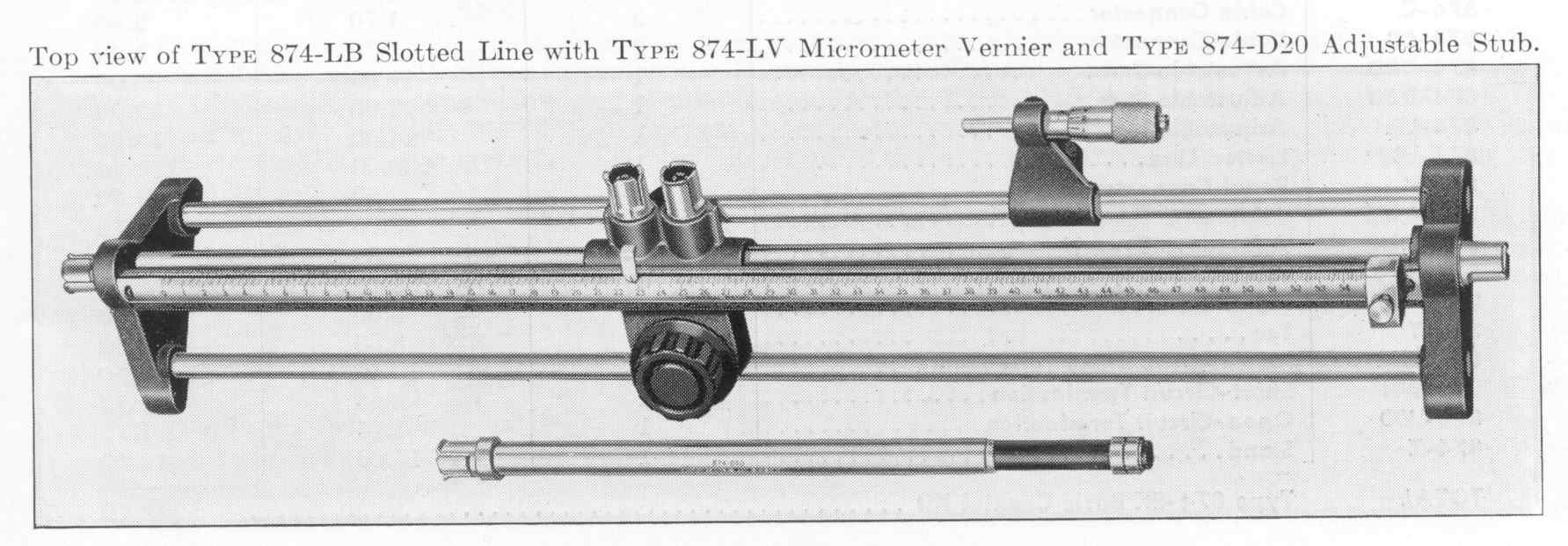
Type 874-LBA Slotted Line
GR was famous for its line of microwave equipment first that first used Type 874 connectors and later Type 900 precision connectors. Both connectors were “sexless” in that they could connect to a similar one. One of the basic instruments in that line was this slotted line which, with a voltmeter, could measure standing wave ratios. The slotted line could also be used with a motor drive and graphic recorder. This 50 ohm GR slotted line was useful from 300 MHz to 5 GHz.
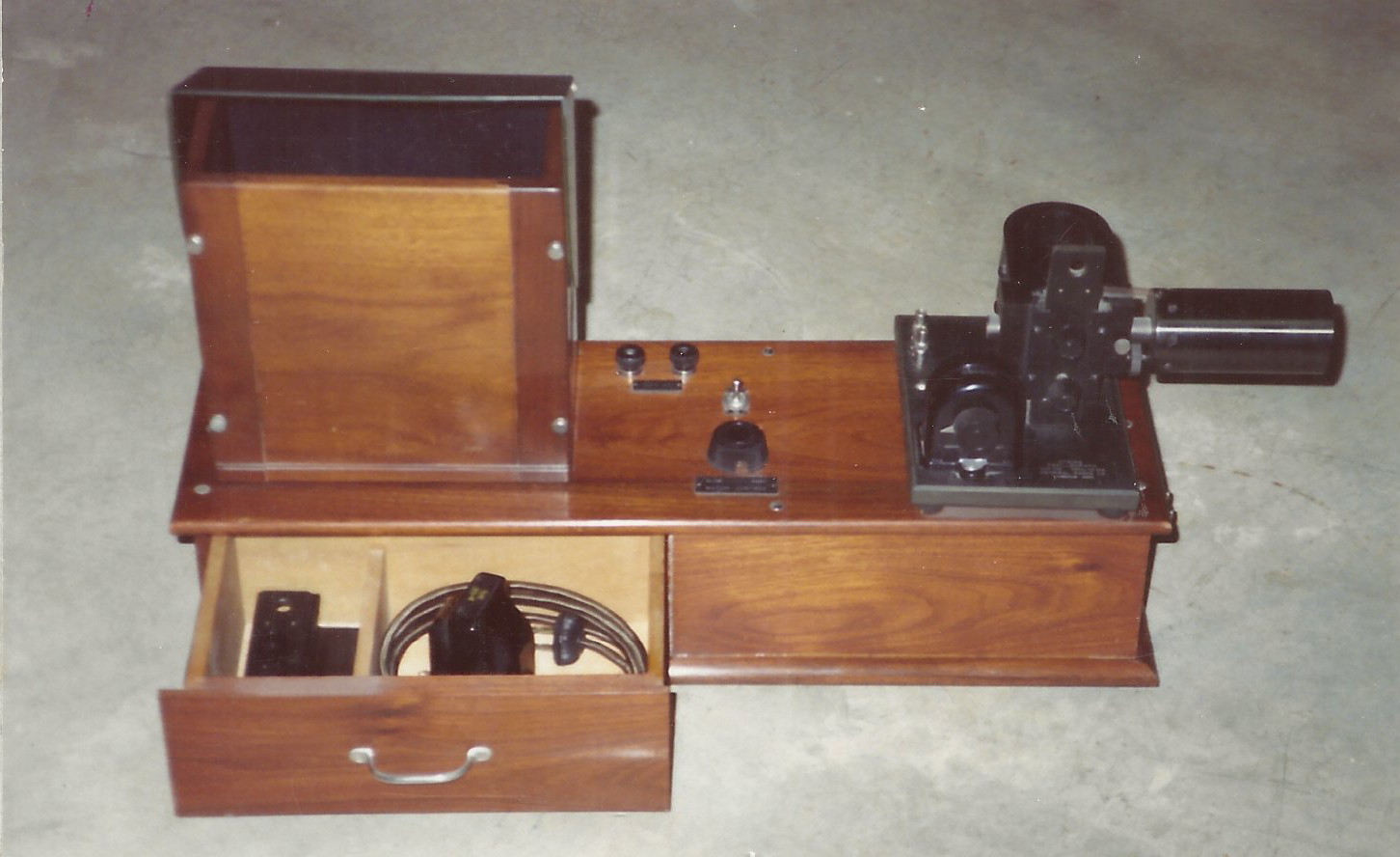
Type 338-L Oscillograph
In this 1928 forerunner to the oscilloscope, a wire carrying the current to be observed was passed through a strong magnetic field. The wire moved proportionally to the current through it. The beam of a strong lamp was focused on the center of the wire and the wire’s shadow fell on a rotating mirror and the on a viewing screen. The rotating mirror provided the time axis and its speed could be adjusted to synchronize with the current waveform. This unit could also be used with the Type 408 Oscillograph Camera which would replace the mirror and viewing screen.
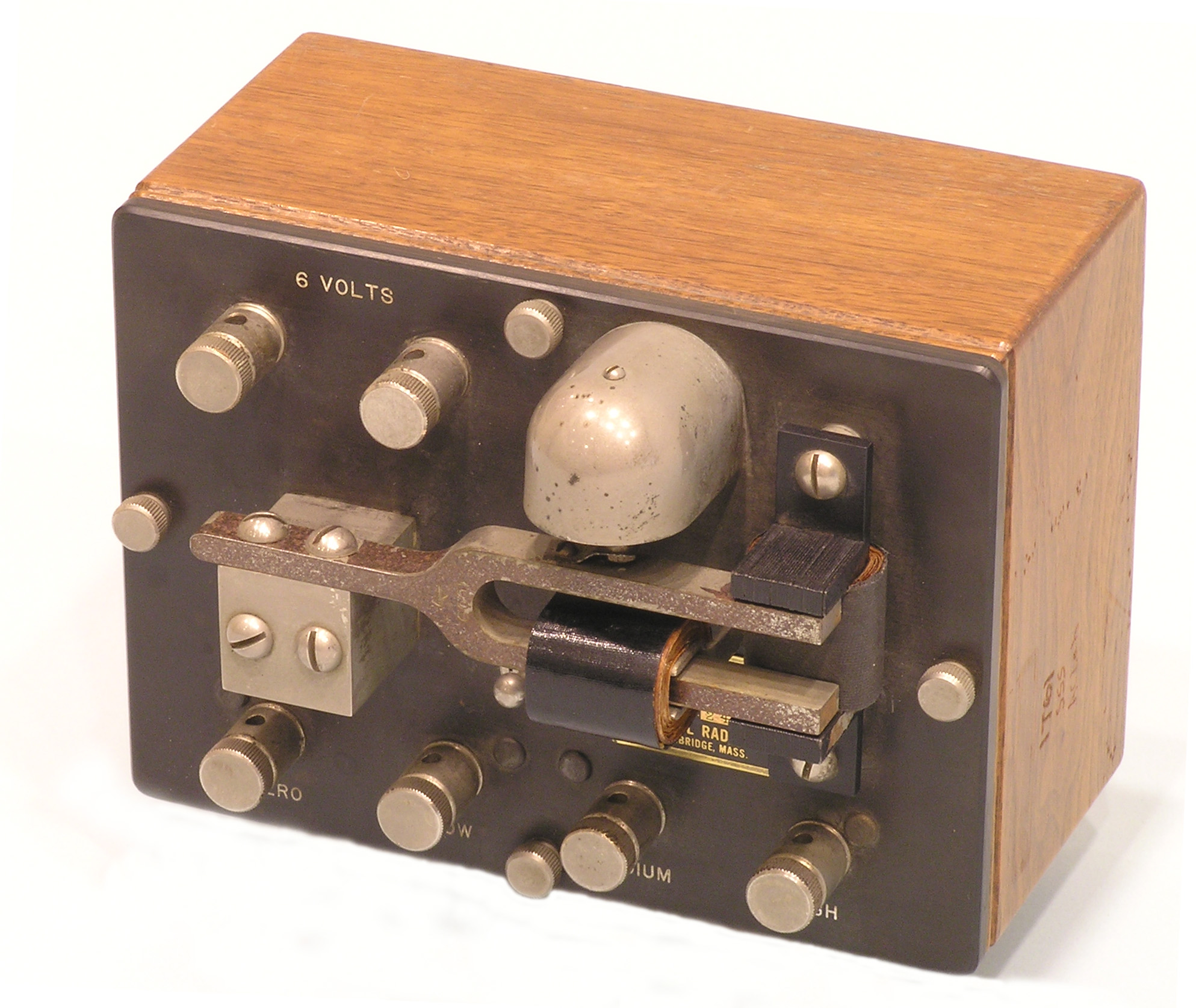
Type 213 Oscillator
Before R-C oscillators, one way go get an accurate low-frequency test signal was to use a tuning-fork oscillator like the GR 213. It used a feedback circuit in which the fork drove a microphone which in turn controlled the current that drove the fork. It provided a stable signal with reasonably low distortion. It came in two standard models, 400 Hz and 1000 Hz, but other frequencies were available on special order. The 1000 Hz version was announced in 1920.
Type BC-14A Receiver
The BC-14C receiver was a crystal receiver used in WWI by the allies artillery to get target locations from spotters on the ground and in the air. It was copied from the French A-1 receiver. It was first made in 1917 and by General Radio in 1918. It was also made by DeForest, Liberty Electric and Wireless Specialty. Its simple circuit used a variable air inductor, or “variometer”, two variable air capacitors and the crystal rectifier. GR also made the BC-15A Transmitter and in 1919 made the U.S. Army Signal Corps “S.C.R. 112 Battalion <>Regiment Set Box” which was both a transmitter and a receiver.
Type 759 Sound- Level Meter
GR was known for its line of sound measurements equipment including this classic, 1937, sound- level meter designed by L. E. Packard. The first in the line was the Type 559 Noise Meter by H. H. Scott (1933), and several such meters followed, including several modern sound-level meters still sold by IET Labs. GR also made a line of sound and vibration analyzers and both dynamic and condenser microphones as well as associated equipment.
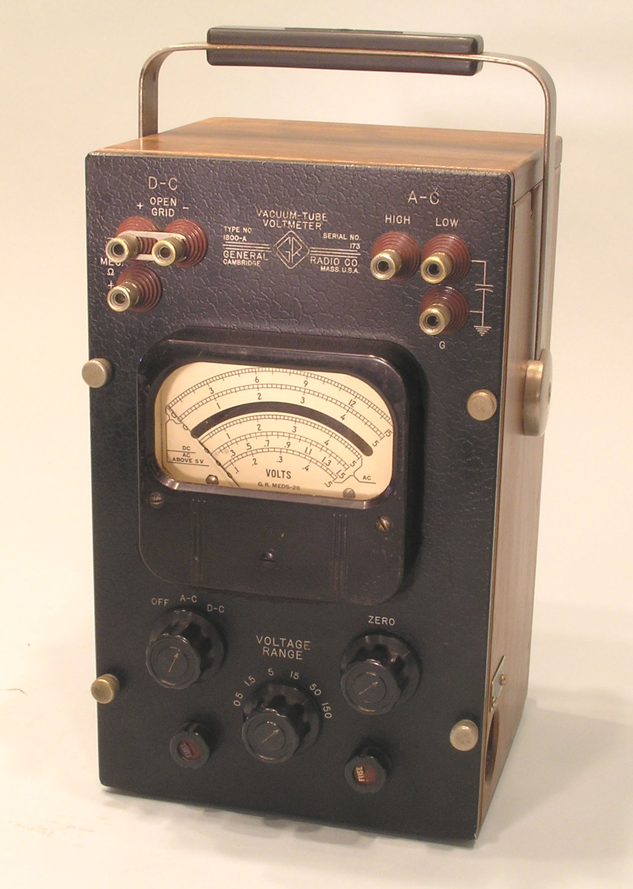
Type 1800 Vacuum-Tube Voltmeter
While several popular General Radio VTVMs preceded and followed the Type 1800, this classic was probably the most famous. It was announced in 1946 and designed by C. E. Woodward with suggestions from D. B. Sinclair who later became a GR President. It measured both AC and DC voltages over wide voltage ranges and its rectifying probe allowed useful measurements to over 300 MHz.
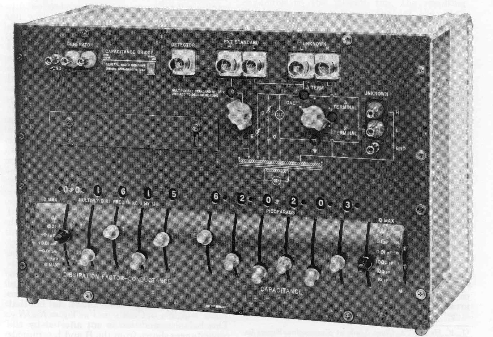
Type 1615 Capacitance Bridge
GR was famous for its precision bridges, particularly for the transformer-ratio-arm bridges designed by J. F. Hersh. The Type 1615 and even more precise Type 1616 were used in electrical standards laboratories around the world. The 1615’s measured capacitance over a wide range with sensitivity and resolution to measure down to 10 aF (10-17F) and the 1616 down to 0.1 aF (10-19F). The 1615 made both 2-terminal and 3-terminal measurements

