What is an LCR Meter?
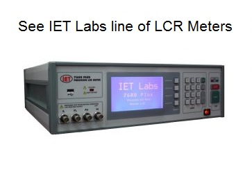
Looking to Buy an LCR Meter.
IET Labs is a premier manufacturer of the some of the world's most popular LCR Meters. Click here to see our instruments.
Looking for detailed technical information on impedance and LCR.
Click the link to the LCR primer above.
Looking for a quick basic understanding of an LCR Meter and relevant features.
Read More Below:
LCR Meter Defined
An LCR meter (Inductance (l), Capacitance (C), and Resistance (R)) is an instrument used to measure the inductance, capacitance, and resistance of a component, sensor or another device that’s operation depends upon capacitance, inductance or resistance. IET Labs manufactures a wide variety of LCR Meters , Capacitance Meters , and Resistance meters for high resistance and low resistance measurement. In addition, IET Labs also manufactures a variety of Resistance , Capacitance , Inductance Standards for all of your calibration needs.
Digital LCR meters measure the current (I) flowing through a device under test (DUT), the voltage (V) across the DUT, and the phase angle between the measured V and I. From these three measurements, all impedance parameters can then be calculated. A typical LCR meter has four terminal Kelvin connection to connect to the DUT device under test. The Kelvin connection minimizes errors due to cabling and connection to the DUT.
Types of LCR Meters
There are a variety of LCR meters from handheld to benchtop.
Handheld DMM with capacitance measurement are designed primarily as a DMM but use a DC technique to measure capacitance. The measurement of capacitance is based upon measuring the RC time constant of the DUT and calculating capacitance. Generally meters in this class have an accuracy of +/-1%.
Handheld LCR meters have the advantage of being lightweight, portable and battery operated.
Benchtop LCR meters generally offer more features than handheld such as programmable frequencies, better measurement accuracy to 0.01%, computer control and data collect for automated applications. Advanced feature such as DC bias voltage, and DC bias current and sweep capability are common. LCR meters in this category are used for AC calibration of inductance, capacitance and resistance standards, dielectric constant measurements with a variety of dielectric cells , and production testing of components and sensors.
Test Frequency
Electrical components need to be tested at the frequency for which the final product/application will be utilized. An instrument with a wide frequency range and multiple programmable frequencies provides this platform. Common measurement frequencies are 50/60Hz, 120Hz, 1kHz, 100kHz and 1MHz. LCR meters with programmable frequencies provide the most flexibility, in matching frequency of measurement to the frequency the DUT will actually be used at or use in R&D applications where frequency characterization is useful to determine useful frequency range or resonance. Most LCR meters today use an AC test signal over a frequency range of 10 Hz to 2MHz.
Test Voltage
The AC output voltage of most LCR meters can be programmed to select the signal level applied to the DUT. Generally, the programmed level is obtained under an open circuit condition. A source resistance (Rs, internal to the meter) is effectively connected in series with the ac output and there is a voltage drop across this resistor. When a test device is connected, the voltage applied to the device depends on the value of the source resistor (Rs) and the impedance value of the device.
Accuracy/Speed
Classic trade-off. The more accurate your measurement the more time it takes and conversely, the faster your measurement speed the less accurate your measurement. That is why most LCR meters have three measurement speeds: slow, medium and fast. Depending on the device under test, the choice is yours to select accuracy or speed. Averaging and median mode can also help to improve measurement accuracy but increase measurement time. It is also important to look into the accuracy formulas in the manuals as the actual accuracy fo the measurement varies depending upon, frequency, voltage and impedance of the DUT.
Measurement Parameters
Primary parameters L, C and R are not the only electrical criteria in characterizing a passive component and there is more information in the Secondary parameters than simply D and Q. Measurements of conductance (G), susceptance (B), phase angle (q) and ESR can more fully define an electrical component, sensor or material.
- Bridging the LCR measurement gap An excellent Evaluation Engineering article, written by Tom Lecklider, Senior Technical Editor, November 2014 discussing different types of LCR Meters and various manufacturers including QuadTech/IET Labs.