What is Impedance?
Electrical impedance (Z), is the total opposition that a circuit presents to alternating current. Impedance changes according to the components in the circuit and the frequency of the applied AC. Impedance can include resistance (R), inductive reactance (X L), and capacitive reactance (XC). It is not simply the algebraic sum of the resistance, inductive reactance, and capacitive reactance. Inductive reactance and capacitive reactance are 90o out of phase with the resistance, so that their maximum values occur at different times. Therefore, vector addition must be used to calculate impedance.
In a circuit supplied by DC, resistance is the ratio of applied voltage (V) to resulting current (I). This is Ohm’s Law.

An alternating current regularly reverses its polarity. When an AC circuit contains only resistance, the circuit resistance is determined by Ohm’s Law, too.
However, when capacitance and/or inductance are present in an AC circuit, they cause the voltage and current to be out of phase. Therefore, Ohm’s law must be modified by substituting impedance (Z) for resistance. Ohm's Law becomes: Z = V/I, where Z is a complex number.
![]()
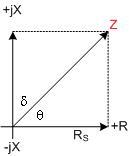
Z is a complex number; i.e., it has a real component (R) and an imaginary component (jX). The imaginary component represents any point on the AC waveform.
Phase Shift
The resistance is always in-phase with the voltage. Therefore a phase shift is always relative to the resistance line. When the circuit has more resistance relative to inductive reactance, the impedance line moves toward the resistance line (X axis) and the phase shift decreases. When the circuit produces more inductive reactance relative to resistance, the impedance line shifts toward the inductive reactance line (Y axis) and the phase shift increases.
The impedance in a circuit with resistance and inductive reactance can be calculated using the following equation. If capacitive reactance was present in the circuit, its value would be added to the inductance term before squaring.
![]()
The phase angle of the circuit can be calculated using the equation below. If capacitive reactance was present in the circuit, its value would be subtracted from the inductive reactance term.
![]()
A phase shift can be drawn in a vector diagram showing a series impedance, Z, its real part Rs (series resistance), its imaginary part jXs (series reactance), and the phase angle θ.
ω= 2πf
Figure 1. A Set of Vector Diagrams
When there is either inductance or capacitance in a circuit, voltage and current are out of phase.
Inductance - Voltage across the inductor is maximum when the rate of change of the current is greatest. For an AC (sinusoidal) wave form, this is at the point where the actual current is zero. The voltage applied to an inductor reaches its maximum value a quarter-cycle before the current does, and the voltage is said to lead the current by 90o.
Capacitance - Current flowing through the capacitor is directly proportional to the value of the capacitor itself (high value capacitors charge more slowly), and is directly proportional to the change in capacitor voltage over time. Current applied to a capacitor reaches its maximum value a quarter-cycle before the voltage; current leads the voltage by 90o.across the capacitor.
Series vs. Parallel Equivalencies
Which should be measured, series or parallel parameters? It depends on the purpose of the measurement. For incoming inspection and production measurements on passive components usually the series values is specified in EIA and MIL standards. These standards also specify test frequencies and other test conditions.
To determine the DC value of a resistor using AC measurements, use series measurements of low-valued resistors (say under 1k ); use parallel measurements of high-valued ones. In most cases, this avoids errors due to series inductance and parallel lumped capacitance. Also, use a low test frequency. Note that sometimes an AC measurement can give the correct DC value better than a DC measurement because thermal voltage and drift errors are avoided and measurement sensitivity is apt to be higher.
Other cases where parallel measurements are preferred are when measuring very low values of capacitance, when making measurements on dielectric and magnetic materials, and, of course, when trying to determine the separate values of two components in parallel. Very often the D of a capacitor is less than .01 so that it doesn't make any difference which is measured because the difference between the series and parallel values is less than .01%. Likewise, the Q of a resistor is usually less than .01 so that either resistance quantity can be measured.
An equivalent circuit for this impedance would put Rs and Xs in series, hence subscript ‘s’.
![]()
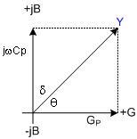
The reciprocal of Z is Admittance (Y), which is also a complex number having a real part Gp (parallel conductance) and an imaginary part jBp (parallel susceptance) with a phase angle φ.
For a complete list of Impedance Terms & Equations, please see Page 65.
Resistance, R, can be specified by a single real number and the unit is the Ohm (Ω). The conductance, G, of a device is the reciprocal of its resistance: G = 1/R. The unit of conductance is the Siemen (formerly mho, 'Ohm' spelled backwards).
For AC, the ratio of voltage to current is a complex number because AC voltages and currents have phase as well as magnitude. This complex number is called impedance, Z, and is the sum of a real number, R, and an imaginary one, jX, (where j = -1 ). Thus, Z = R + jX. The real part is the AC resistance and the imaginary part is the reactance. Both have units of Ohms.
Reactance comes in two types, inductive and capacitive. The reactance of an inductive element is L, where L is its inductance and = 2πf (where f = frequency). The reactance of a capacitive element is negative, -1/ C, where C is its capacitance. The negative sign occurs because the impedance of a pure capacitor is 1/j C and 1/j = -j.
Because the impedance of two devices in series is the sum of their separate impedances, consider an impedance as the series combination of an ideal resistor and an ideal capacitor or inductor. This is the series equivalent circuit of an impedance comprising an equivalent series resistance and an equivalent series capacitance or inductance. Using the subscript s for series, we have:
![]()
For a network having many components, the element values of the equivalent circuit change with the frequency. This is also true of the values of both the inductive and the capacitive elements of the equivalent circuit of a single, actual component (although the changes are usually very small).
Impedance is represented, at any specific frequency, by an equivalent circuit. The values of these elements or parameters depend on which representation is used, series or parallel, except when the impedance is purely resistive or purely reactive. In such cases only one element is necessary and the series or parallel values are the same.
Admittance, Y, is the reciprocal of impedance as shown in equation 2:
![]()
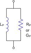
It, too, is a complex number, having a real part, the AC conductance G, and an imaginary part, the susceptance B. Because the admittances of parallel elements are added, Y can be represented by a parallel combination of an ideal conductance and a susceptance, where the latter is either an ideal capacitance or an ideal inductance. Using the subscript p for parallel elements, we have equation 3:
![]()
In general, Gp is not equal to 1/Rs and Bp is not equal to 1/Xs (or -1/Xs) as one can see from the calculation in equation 4.
Thus Gp = 1/Rs only if Xs = 0, which is the case only if the impedance is a pure resistance; and Bp = -1/Xs (note the minus sign) only if Rs = 0, that is, the impedance is a pure capacitance or inductance.
Two other quantities, D and Q, are measures of the "purity" of a component, that is, how close it is to being ideal or containing only resistance or reactance. D, the dissipation factor, is the ratio of the real part of impedance, or admittance, to the imaginary part. Q, the quality factor, is the reciprocal of this ratio as illustrated in equation 5.
![]()
An in depth discussion of The History of Impedance Measurements by Henry P. Hall is another well written article on the topic of impedance measurements.